
Concept explainers
Videos
(a)
To derive: The expression for the frequency of oscillation
(a)
Answer to Problem 15.30P
The expression for the frequency of oscillation is
Explanation of Solution
Given:
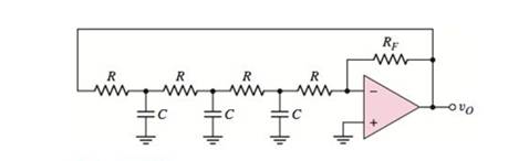
Consider the circuit shown below.

Calculation:
The non-inverting terminal of op-amp is grounded. Hence, the voltage
From virtual ground, the voltage at non-inverting terminal is equal to voltage at inverting terminal
Use KCL at the node
Use KCL at the node
Use KCL at the node
Substitute
Substitute equation (3) in equation (2),
Substitute equation (4) in equation (1),
Use KCL at the node
Substitute
Substitute
The transfer function is given by.
To find the frequency oscillation, set
From the Barkhausen criterion, the condition for oscillation is that
To satisfy the condition
Conclusion:
Therefore, the expression for the frequency of oscillation is
(b)
The condition of oscillation.
(b)
Answer to Problem 15.30P
The condition of oscillation is
Explanation of Solution
Given:
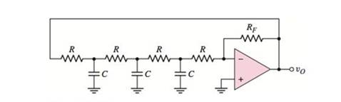
Consider the circuit shown below.
Calculation:
Substitute
The condition for oscillation is that
Substitute
Therefore, the required condition for oscillation is
Conclusion:
Therefore, the required expression for the frequency of oscillation is
(c)
To find: The values of capacitor and
(c)
Answer to Problem 15.30P
The required values are
Explanation of Solution
Given:
Consider the circuit shown below.
Calculation:
Substitute
Thus, the required feedback resistance is
Substitute
Conclusion:
Therefore, the required values are
Want to see more full solutions like this?
Chapter 15 Solutions
Microelectronics: Circuit Analysis and Design


 Introductory Circuit Analysis (13th Edition)Electrical EngineeringISBN:9780133923605Author:Robert L. BoylestadPublisher:PEARSON
 Delmar's Standard Textbook Of ElectricityElectrical EngineeringISBN:9781337900348Author:Stephen L. HermanPublisher:Cengage Learning
 Programmable Logic ControllersElectrical EngineeringISBN:9780073373843Author:Frank D. PetruzellaPublisher:McGraw-Hill Education
 Fundamentals of Electric CircuitsElectrical EngineeringISBN:9780078028229Author:Charles K Alexander, Matthew SadikuPublisher:McGraw-Hill Education
 Electric Circuits. (11th Edition)Electrical EngineeringISBN:9780134746968Author:James W. Nilsson, Susan RiedelPublisher:PEARSON
 Engineering ElectromagneticsElectrical EngineeringISBN:9780078028151Author:Hayt, William H. (william Hart), Jr, BUCK, John A.Publisher:Mcgraw-hill Education,